Cables, Harnesses and Enclosures: A Product Design Checklist
Turning a working board into a finished product? Plan wire harnesses, connectors, strain relief and enclosure fit early with this practical checklist.
Microplacer team · 15 November 2026 · 3 min read
 EMS & Product
Your board works on the bench. Then you try to fit it in a case, plug in the sensors and close the lid — and suddenly a connector sits two millimetres too low, a cable is too short and the USB port faces the wrong wall. Most of these problems are not electronics problems at all. They are wiring and mechanical decisions that were left until the end. This checklist helps you make them early.
Why harness and mechanical planning should start early
The PCB layout fixes where every connector, mounting hole and tall component sits. Once boards are made, moving a connector means a new revision. If you sketch the enclosure and the cable routes while the layout is still open, you can place connectors where the cables naturally want to go, keep heavy cables away from delicate parts and leave room for fingers and tools during assembly.
- Decide which side of the product each cable enters and exits before placing connectors on the board.
- Note the height of the tallest parts — electrolytic capacitors, relays, heat sinks — against the inside of the case.
- Think about how the product will be assembled: which board goes in first, and can every connector still be reached?
Specifying a wire harness: wire gauge, length, connectors, labels
A wire harness bundles several wires, their crimped terminals and connectors into a single pre-built assembly that drops into the product. A single cable with a connector at each end is usually called a cable assembly. Either way, the person building it can only follow what is written down, so a clear specification is the whole game.
| What to specify | What to write | Common mistake |
|---|---|---|
| Wire gauge | AWG or mm² for each wire, sized for its current and length | Using one thin gauge for everything, including power lines |
| Insulation & colour | Insulation type, colour, any temperature or flexibility need | Leaving colours "any" and then struggling to trace faults |
| Length | Length of each wire or branch, plus the allowed tolerance | Measuring point-to-point on the CAD model with no slack for routing |
| Connectors & terminals | Exact housing and terminal part numbers from one compatible family | Naming the housing but not the matching crimp terminal |
| Pin-out table | From connector & pin → to connector & pin for every wire | Drawing pin 1 from the wrong side of the connector |
| Labels & finish | Marker text and position, sleeving, heat-shrink, ties or tape | No labels on harnesses with several identical connectors |
Connector choice and strain relief
Connectors are where most field failures in wiring start, usually because a cable gets pulled, flexed or vibrated more than expected. A few habits make a big difference:
- Choose locking connectors for anything that moves or vibrates. Friction-fit headers can work loose over time.
- Make connectors that must never be swapped different in size, pin count or keying, so they cannot be plugged into the wrong socket.
- Rate contacts for the real current with some margin, and spread high currents over more than one pin if needed.
- Never let the solder joints of a board connector carry the pull of a cable. Clamp, tie or grommet the cable to the enclosure first.
- Leave a small service loop so the cable is not tight when the lid is opened or closed.
When it comes to build quality, cable and harness work is normally judged against IPC/WHMA-A-620. If your product calls for a specific class under that standard, write it on the drawing.
Enclosure fit, mounting holes and connector cut-outs
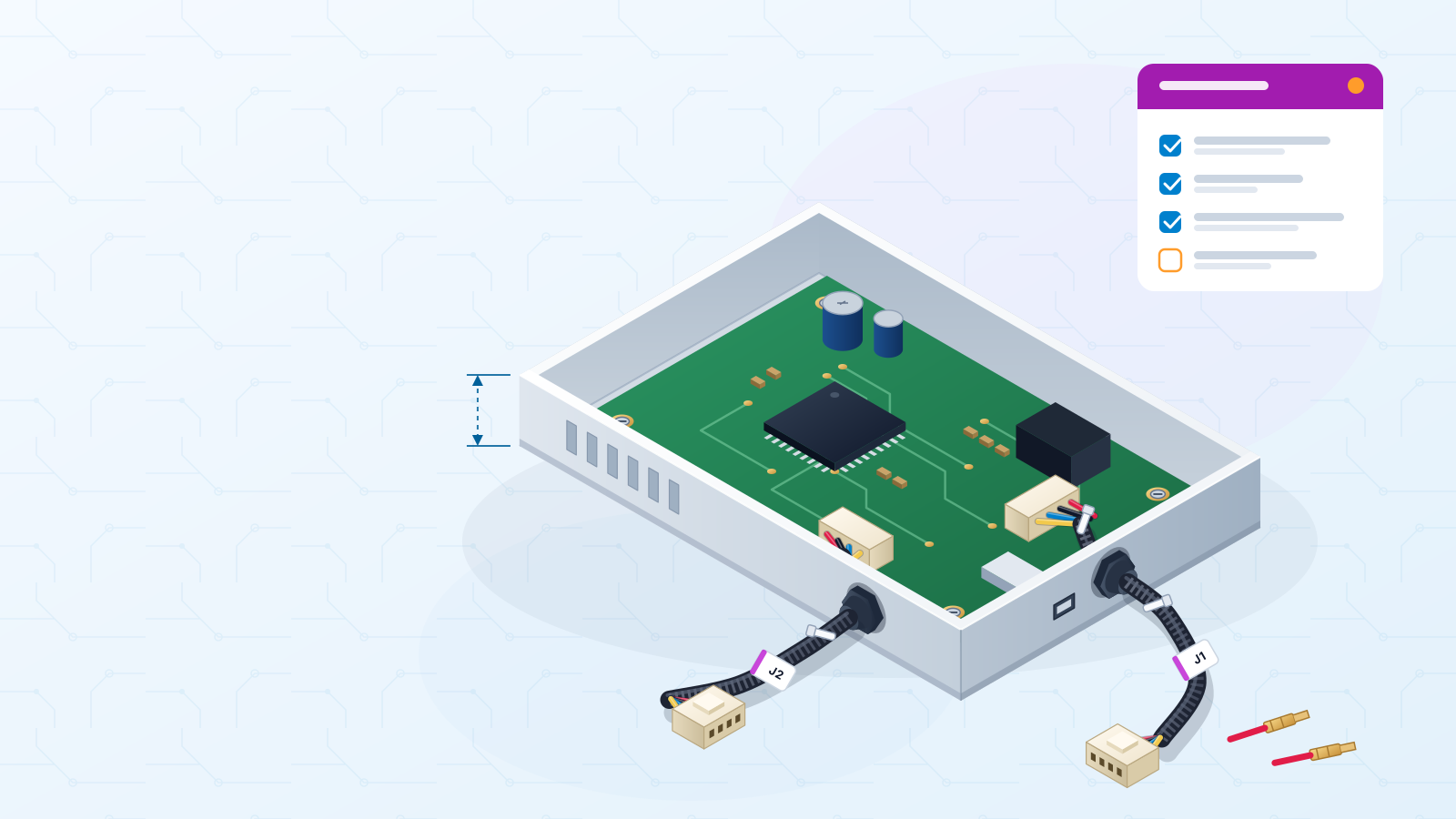
Treat the board outline and the enclosure as one design. A simple 3D check — even a rough model — catches most clashes before you order anything.
Things to check against the case
- 1Mounting holes line up with the case bosses, with clearance around screw heads and standoffs.
- 2Edge connectors sit at the right height and distance from the wall so the mating plug fully seats through the cut-out.
- 3Cut-outs allow for the plug body and cable bend, not just the socket on the board.
- 4LEDs, buttons and displays line up with their windows or light pipes.
- 5Hot parts have airflow or a path to conduct heat away, and cables do not rest on them.
- 6There is space for the harness itself: bundles, ties and connectors take more room than single wires on a drawing.
When to bring in product design and development support
You do not need outside help for every project. But it is worth asking when the product is moving from one hand-built unit to something you will build again and again. Typical signs:
- You have a working breadboard or dev-kit setup and need a proper PCB, a case and a first small batch.
- An existing product needs a new revision — an obsolete part, a smaller board or easier assembly.
- You want an independent design review for manufacturability, part availability and enclosure fit before spending on prototypes.
- The product needs safety, EMC or wireless approvals later. Design choices affect whether it can pass, so mention them at the start; the testing itself is a separate step done at a suitable lab.
A good process moves through requirements, schematic, layout, enclosure check, prototypes and a pilot build, with a review at each stage. Plan for at least one prototype revision — it is normal, and far cheaper than a fix after production.
Final product-readiness checklist
- 1Requirements written down: functions, power source, environment, size limit and expected quantity.
- 2Board outline, mounting holes and connector positions checked against the enclosure.
- 3Harness drawing with wire gauge, lengths, tolerances, colours, labels and exact connector and terminal part numbers.
- 4Pin-out table cross-checked against the PCB schematic connectors.
- 5Strain relief and service loops defined for every external cable.
- 6Key parts checked for availability before the design is frozen.
- 7A test plan: how each board and each harness will be checked before it goes into the box.
- 8Board manufacturing and assembly files frozen at the same revision as the released drawings.
Ready for the next step? Send your harness drawing or sketch through our wire harness page, or talk to us about the bigger picture on product design & development. When boards, cables and the case come together as one unit, our box build assembly page explains how that works.
#wire-harness#cable-assembly#enclosure-design#product-design#connectors
Get an instant PCB quote